13.2. Creare Layer
I layer possono essere creati in molti modi, tra cui:
empty layers from scratch
layers from existing layers
layers from the clipboard
layers as a result of an SQL-like query based on one or many layers (virtual layers)
QGIS also provides tools to import/export from/to different formats.
13.2.1. Creare nuovi layer Vettore
QGIS allows you to create new layers in different formats. It provides tools for creating GeoPackage, Shapefile, SpatiaLite, GPX format and Temporary Scratch layers (aka memory layers). Creation of a new GRASS layer is supported within the GRASS plugin.
13.2.1.1. Creare un nuovo vettore GeoPackage
To create a new GeoPackage layer, press the  button in the
menu or from the
Data Source Manager toolbar.
The New GeoPackage Layer dialog will be displayed as shown in
figure_create_geopackage.
button in the
menu or from the
Data Source Manager toolbar.
The New GeoPackage Layer dialog will be displayed as shown in
figure_create_geopackage.
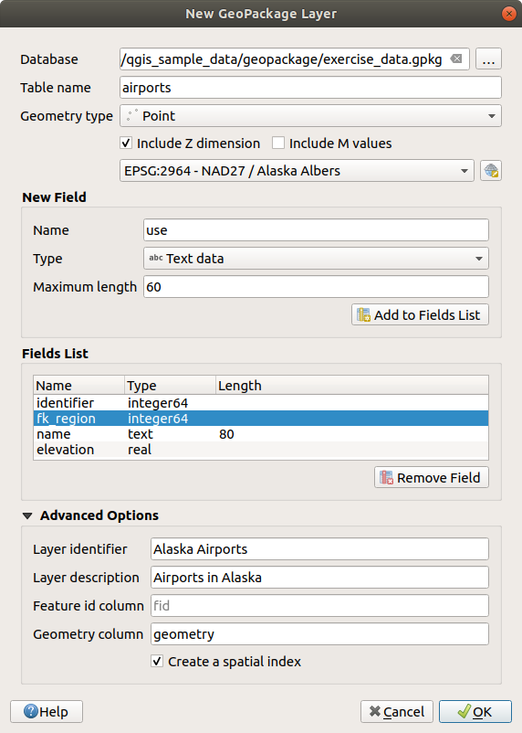
Fig. 13.13 Finestra di dialogo creazione Nuovo vettore GeoPackage
The first step is to indicate the database file location. This can be done by pressing the … button to the right of the Database field and select an existing GeoPackage file or create a new one. QGIS will automatically add the right extension to the name you provide.
Give the new layer / table a name (Table name)
Define the Geometry type. If not a geometryless layer, you can specify whether it should Include Z dimension and/or Include M values.
Specify the coordinate reference system using the
 button
To add fields to the layer you are creating:
Enter the Name of the field
Select the data Type. Supported types are Text data, Whole number (both integer and integer64), Decimal number, Date and Date and time, Binary (BLOB) and Boolean.
Depending on the selected data format, enter the Maximum length of values.
Click on the
 Add to Fields List button
Reproduce the steps above for each field you need to add
Once you are happy with the attributes, click OK. QGIS will add the new layer to the legend, and you can edit it as described in section Modifica di un layer esistente.
By default, when creating a GeoPackage layer, QGIS generates a
Feature id column called fid which acts as the
primary key of the layer. The name can be changed.
The geometry field, if availabe, is named geometry, and you can
choose to Create a spatial index on it.
These options can be found under the Advanced Options
together with the Layer identifier (short human readable
name of the layer) and the Layer description.
Further management of GeoPackage layers can be done with the DB Manager.
13.2.1.2. Creare un nuovo layer Shapefile
To create a new ESRI Shapefile format layer, press the  button in the
menu or from the
Data Source Manager toolbar.
The New Shapefile Layer dialog will be displayed as shown in
figure_create_shapefile.
button in the
menu or from the
Data Source Manager toolbar.
The New Shapefile Layer dialog will be displayed as shown in
figure_create_shapefile.
Provide a path and file name using the … button next to File name. QGIS will automatically add the right extension to the name you provide.
Next, indicate the File encoding of the data
Choose the Geometry type of the layer (point, multipoint, line or polygon)
Specify whether the geometry should have Z (+ M values) or M values
Specify the coordinate reference system using the
button
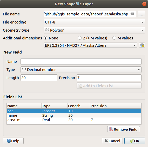
Fig. 13.14 Finestra di dialogo creazione nuovo Layer Shapefile
To add fields to the layer you are creating:
Enter the Name of the field
Select the data Type. Only Decimal number, Whole number, Text data and Date attributes are supported.
Depending on the selected data format, enter the Length and Precision.
Click on the
Add to Fields List buttonReproduce the steps above for each field you need to add
Once you are happy with the attributes, click OK. QGIS will add the new layer to the legend, and you can edit it as described in section Modifica di un layer esistente.
By default, a first integer id column is added but can be removed.
13.2.1.3. Creare un nuovo layer SpatiaLite
To create a new SpatiaLite layer, press the  button in the menu or from the Data Source Manager toolbar.
The New SpatiaLite Layer dialog will be displayed as shown in
Figure_create_spatialite.
button in the menu or from the Data Source Manager toolbar.
The New SpatiaLite Layer dialog will be displayed as shown in
Figure_create_spatialite.
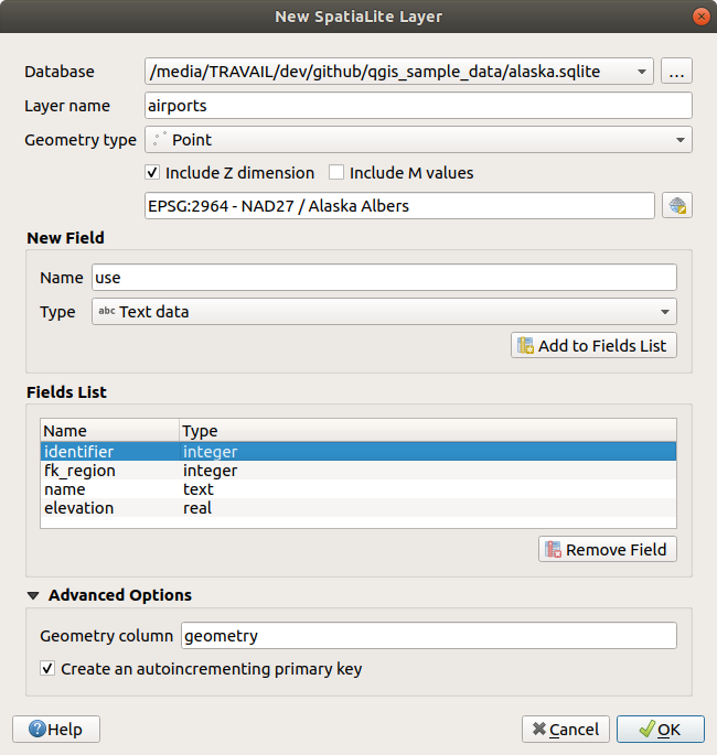
Fig. 13.15 Finestra di dialogo creazione Nuovo layer SpatiaLite
The first step is to indicate the database file location. This can be done by pressing the … button to the right of the Database field and select an existing SpatiaLite file or create a new one. QGIS will automatically add the right extension to the name you provide.
Provide a name (Layer name) for the new layer
Define the Geometry type. If not a geometryless layer, you can specify whether it should Include Z dimension and/or Include M values.
Specify the coordinate reference system using the
button.
To add fields to the layer you are creating:
Enter the Name of the field
Select the data Type. Supported types are Text data, Whole number and Decimal number.
Click on the
Add to Fields List buttonReproduce the steps above for each field you need to add
Once you are happy with the attributes, click OK. QGIS will add the new layer to the legend, and you can edit it as described in section Modifica di un layer esistente.
If desired, you can select  Create an autoincrementing
primary key under the guilabel:Advanced Options section. You can also rename
the Geometry column (
Create an autoincrementing
primary key under the guilabel:Advanced Options section. You can also rename
the Geometry column (geometry by default).
Further management of SpatiaLite layers can be done with DB Manager.
13.2.1.4. Creare un nuovo layer GPX
To create a new GPX file, you first need to load the GPS plugin.
 opens the Plugin Manager Dialog. Activate the
GPS Tools checkbox.
opens the Plugin Manager Dialog. Activate the
GPS Tools checkbox.
When this plugin is loaded, choose
 from the menu.
In the dialog, choose where to save the new file and press Save.
Three new layers are added to the Layers Panel:
from the menu.
In the dialog, choose where to save the new file and press Save.
Three new layers are added to the Layers Panel:
waypoints, routes and tracks.
13.2.1.5. Creare un nuovo vettore temporaneo
Temporary Scratch Layers are in-memory layers, meaning that they are not saved on disk and will be discarded when QGIS is closed. They can be handy for storing features you temporarily need or as intermediate layers during geoprocessing operations.
To create a new Temporary Scratch layer, choose the  entry in the
menu or in the Data
Source Manager toolbar.
The New Temporary Scratch Layer dialog will be displayed as shown in
figure_create_temporary. Then:
entry in the
menu or in the Data
Source Manager toolbar.
The New Temporary Scratch Layer dialog will be displayed as shown in
figure_create_temporary. Then:
Provide the Layer name
Select the Geometry type. Here you can create a:
Layer di tipo
No geometry, utilizzato come semplice tabella,layer
PuntooMulti punto,layer
LineString/CompoundCurveoMultiLineString/MultiCurve,layer
Polygon/CurvePolygonoMultiPolygon/MultiSurface.
Specify the coordinate reference system using the
button.
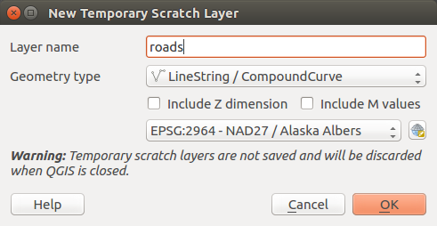
Fig. 13.16 Finestra di dialogo creazione nuovo vettore temporaneo
By default, a new temporary scratch layer is created without any attributes. You
can later add them using the New Field button in the
layer’s attribute table dialog or the Fields tab of its
properties dialog.
You can also create prepopulated temporary scratch layers using e.g. the
clipboard (see Creare nuovi layer dagli appunti) or as a result of a Processing
algorithm.
Suggerimento
Salvataggio permanente di un vettore temporaneo su disco
To avoid data loss when closing a project with temporary scratch layers, you can save these layers to any vector format supported by QGIS:
cliccando sull’icona
 accanto al layer;
selezionando Rendi permanente nel menu contestuale del layer;
using the entry from the contextual menu or the menu.
Each of these commands opens the Save Vector Layer as dialog described in the Creare nuovi layer da layer esistente section and the saved file replaces the temporary one in the Layers panel.
13.2.2. Creare nuovi layer da layer esistente
Sia i layer raster che vettoriali possono essere salvati in un formato diverso e/o riproiettati in un diverso sistema di riferimento di coordinate (SR) usando il menu o facendo clic destro sul layer nel pannello Layer e selezionando:
for raster layers
or for vector layers.
Drag and drop the layer from the layer tree to the PostGIS entry in the Browser Panel. Note that you must have a PostGIS connection in the Browser Panel.
13.2.2.1. Parametri comuni
La finestra di dialogo Salva Layer come…. mostra diversi parametri per cambiare il risultato con il salvataggio del layer. Tra i parametri comuni per raster e vettori ci sono:
File name: the location of the file on the disk. It can refer to the output layer or to a container that stores the layer (for example database-like formats such as GeoPackage, SpatiaLite or Open Document Spreadsheets).
SR: può essere cambiato per riproiettare i dati.
Estensione (i valori possibili sono Estensione del Layer, Estensione della mappa o Estensione definita dall’utente)
Aggiungi il file salvato sulla mappa per aggiungere il nuovo layer alla mappa
Tuttavia, alcuni parametri sono specifici per i formati raster e vettoriali
13.2.2.2. Parametri specifici per i Raster
A seconda del formato di esportazione, alcune di queste opzioni potrebbero non essere disponibili:
Modalità uscita (può essere Dati grezzi o Immagine visualizzata)
Formato: esportazioni in qualsiasi formato raster che GDAL può scrivere, come GeoTiff, GeoPackage, MBTiles, Geospatial PDF, SAGA GIS Binary GIS Grid, Intergraph Raster, ESRI .hdr Labelled…..
Risoluzione
Opzioni di creazione: utilizzare le opzioni avanzate (compressione file, dimensioni dei blocchi, colorimetria….) quando si generano file, o da predefined create profiles relativi al formato di output o impostando ciascun parametro.
Piramidi creazione
Mattonelle VRT nel caso in cui hai scelto
Crea VRTValori nulli
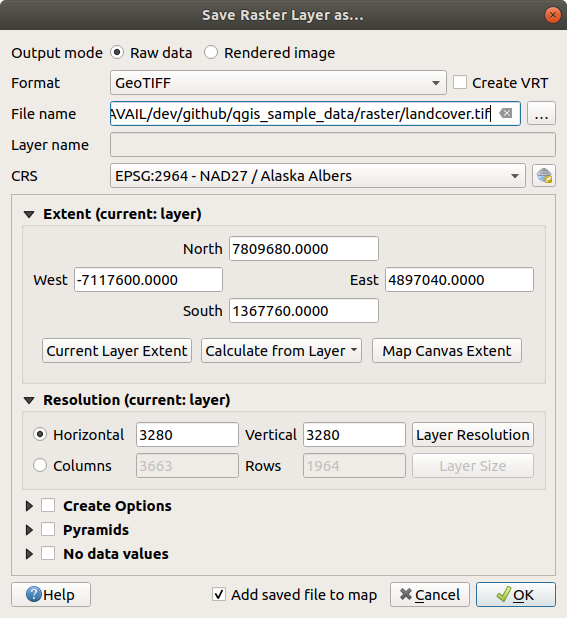
Fig. 13.17 Salvare come un nuovo layer raster
13.2.2.3. Parametri specifici per i Vettori
Depending on the format of export, some of these options may be available:
Format: exports to any vector format GDAL can write to, such as GeoPackage, GML, ESRI Shapefile, AutoCAD DXF, ESRI FileGDB, Mapinfo TAB or MIF, SpatiaLite, CSV, KML, ODS, …
Layer name: available when the File name refers to a container-like format, this entry represents the output layer.
Codifica
Salva solo le geometrie selezionate
Seleziona i campi da esportare e le loro opzioni di esportazione. Nel caso in cui imposti i comportamenti dei campi con alcuni Edit widgets ad esempio «valore», puoi mantenere i valori visualizzati nel layer scegliendo
Sostituisci tutti i valori grezzi selezionati dai valori mostrati.Esporta simbologia: opzione che puoi utilizzare principalmente per l’esportazione del formato DXF e per tutti i formati di file che gestiscono le tipologie di file OGR (vedi nota di seguito) come i formati DXF, KML, i formati tabelle:
Nessuna simbologia: stile di default dell’applicazione che legge i dati
Simbologia geometrie: salva lo stile utilizzando gli stili OGR (vedi la nota di seguito)
Simbologia simboli vettore: salva con gli stili OGR (vedi nota di seguito) ma esporta la stessa geometria più volte se sono utilizzati più simboli
A Scale value can be applied to the latest options
Nota
OGR Feature Styles are a way to store style directly in the data as a hidden attribute. Only some formats can handle this kind of information. KML, DXF and TAB file formats are such formats. For advanced details, you can read the OGR Feature Styles specification document.
Geometria: puoi definire le caratteristiche geometriche del layer in output
geometry type: keeps the original geometry of the features when set to Automatic, otherwise removes or overrides it with any type. You can add an empty geometry column to an attribute table and remove the geometry column of a spatial layer.
Forza multi-tipo: forza la creazione di features multi-geometry nel layer
Includi dimensione z alle geometrie.
Suggerimento
Modificare il tipo di geometria di un layer consente di eseguire cose come salvare una tabella senza geometrie (ad esempio file .csv) in uno shapefile con qualsiasi tipo di geometria (punto, linee, poligono), in modo che le geometrie possano essere aggiunte manualmente a righe con lo strumento  Aggiungi parte.
Datasource Options, Layer Options or Custom Options which allow you to configure advanced parameters depending on the output format. Some are described in Esplorare i formati dati e i campi but for full details, see the GDAL driver documentation. Each file format has its own custom parameters, e.g. for the
GeoJSONformat have a look at the GDAL GeoJSON documentation.
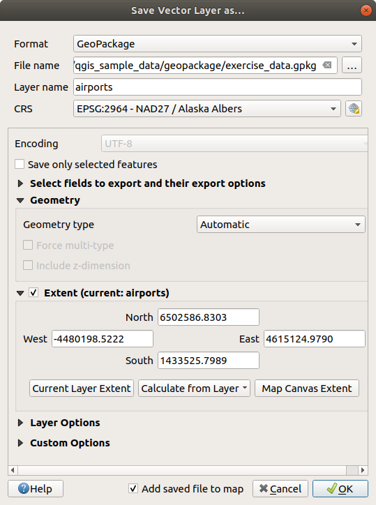
Fig. 13.18 Salvare come un nuovo layer vettoriale
Quando si salva un layer vettoriale in un file esistente, a seconda delle capacità del formato di output (Geopackage, SpatiaLite, FileGDB …), l’utente può decidere se:
sovrascrivere l’intero file
sovrascrivere solo il layer di destinazione (il nome del layer è configurabile)
aggiungere geometrie ad un layer esistente
aggiungere geometrie, aggiungere nuovi campi se ce ne sono.
Sono disponibili opzioni per aggiungere geometrie ai formati come ESRI Shapefile, MapInfo .tab,.
13.2.3. Creazione di nuovi file DXF
Besides the Save As… dialog which provides options to export a
single layer to another format, including *.DXF, QGIS provides another
tool to export multiple layers as a single DXF layer. It’s accessible in the
menu.
Nella finestra di dialogo Esportazione DXF:
Provide the destination file.
Choose the symbology mode and scale (see the OGR Feature Styles note), if applicable.
Selezionare la Codifica dei dati.
Selezionare il SR da applicare: i layer selezionati verranno riproiettati nel SR indicato.
Select the layers to include in the DXF files either by checking them in the table widget or automatically picking them from an existing map theme. The Select All and Deselect All buttons can help to quickly set the data to export.
For each layer, you can choose whether to export all the features in a single DXF layer or rely on a field whose values are used to split the features into layers in the DXF output.
Opzionalmente puoi anche scegliere di:
- Se impostato usa il titolo del layer come nome invece del nome del layer stesso;
- Esporta gli elementi che intersecano l’attuale estensione della mappa;
 Forza risultato 2D (ad esempio per supportare la larghezza della polilinea);
- Esporta le etichette come MTEXT o elementi TEXT.
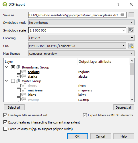
Fig. 13.19 Esportazione di un progetto nella finestra di dialogo DXF
13.2.4. Creare nuovi layer dagli appunti
Le geometrie che si trovano negli appunti possono essere incollate in un nuovo layer. Seleziona alcune geometrie e poi copiale in un nuovo layer usando e scegliendo:
New Vector Layer…: the Save vector layer as… dialog appears (see Creare nuovi layer da layer esistente for parameters)
or Temporary Scratch Layer…: you need to provide a name for the layer
A new layer, filled with selected features and their attributes is created (and added to map canvas).
Nota
Creating layers from the clipboard is possible with features selected and copied within QGIS as well as features from another application, as long as their geometries are defined using well-known text (WKT).
13.2.5. Creazione di layer virtuali
A virtual layer is a special kind of vector layer. It allows you to define a layer as the result of an SQL query involving any number of other vector layers that QGIS is able to open. Virtual layers do not carry data by themselves and can be seen as views.
Per creare un layer virtuale, apri la finestra di dialogo per la creazione di un layer virtuale:
choosing the
 Add/Edit Virtual Layer entry
in the menu;
Add/Edit Virtual Layer entry
in the menu;enabling the
Add Virtual Layer tab in the
Data Source Manager dialog;or using the DB Manager dialog tree.
La finestra di dialogo ti consente di specificare un Nome vettore e una SQL Interrogazione. Questa interrogazione può utilizzare il nome (o id) dei vettori esistenti, così come i nomi dei campi del layer.
Ad esempio, se hai un layer chiamato airports, puoi creare un nuovo layer virtuale da denominare public_airports con una query SQL del tipo:
SELECT *
FROM airports
WHERE USE = "Civilian/Public"
La query SQL verrà eseguita, qualunque sia la struttura di base del vettore airports e anche se questa fonte dati non supporta direttamente le query SQL.
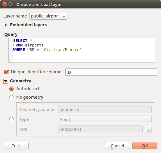
Fig. 13.20 Finestra di dialogo creare layer virtuali
È inoltre possibile creare join e query complesse, ad esempio, per unire aeroporti e informazioni sui paesi:
SELECT airports.*, country.population
FROM airports
JOIN country
ON airports.country = country.name
Nota
Layer virtuali possono essere creati anche usando la finestra di dialogo SQL di Plugin DB Manager.
13.2.5.1. Layer nidificati da usare nelle query
Besides the vector layers available in the map canvas, the user can add layers to the Embedded layers list, which can be used in queries without the need to have them showing in the map canvas or Layers panel.
Per incorporare un layer, fai clic su Aggiungi e inserisci Nome locale, Sorgente dati, Codifica e il percorso della Sorgente dati.
The Import button allows adding layers in the map canvas into the Embedded layers list. Those layers can then be removed from the Layers panel without breaking existent queries.
13.2.5.2. Linguaggi query supportati
Il motore incorporato utilizza SQLite e SpatiaLite per operare.
Ciò significa che puoi utilizzare tuttoi l’SQL che l’installazione locale di SQLite comprende.
Funzioni di SQLite e funzioni spaziali di SpatiaLite possono anche essere utilizzate in una query di layer virtuale. Ad esempio, la creazione di un layer di punti da un layer di solo attributo può essere fatto con una query simile a:
SELECT id, MakePoint(x, y, 4326) as geometry
FROM coordinates
Functions of QGIS expressions possono essere utilizzate anche in una query di layer virtuale.
Per fare riferimento alla colonna geometrica di un layer, utilizzare il nome geometry.
Contrary to a pure SQL query, all the fields of a virtual layer query must
be named. Don’t forget to use the as keyword to name your columns if they
are the result of a computation or a function call.
13.2.5.3. Problemi relativi alle prestazioni
With default parameters, the virtual layer engine will try its best to detect the type of the different columns of the query, including the type of the geometry column if one is present.
This is done by introspecting the query when possible or by fetching the first row of the query (LIMIT 1) as a last resort. Fetching the first row of the result just to create the layer may be undesirable for performance reasons.
The creation dialog parameters:
Unique identifier column: specifies a field of the query that represents unique integer values that QGIS can use as row identifiers. By default, an autoincrementing integer value is used. Defining a unique identifier column speeds up the selection of rows by id.
No geometry: forces the virtual layer to ignore any geometry field. The resulting layer is an attribute-only layer.
Geometry Column: specifies the name of the geometry column.
Geometry Type: specifies the type of the geometry.
Geometry CRS: specifies the coordinate reference system of the virtual layer.
13.2.5.4. Commenti speciali
L’interprete del layer virtuale tenta di determinare il tipo di ogni colonna della query. Se non riesce, viene eseguita la prima riga della query per determinare i tipi colonna.
Il tipo di una particolare colonna può essere specificato direttamente nella query utilizzando alcuni commenti speciali.
La sintassi è la seguente: /*: type*/. Deve essere inserita subito dopo il nome di una colonna. il tipo può essere int per interi, real per numeri a virgola mobile o text.
Ad esempio:
SELECT id+1 as nid /*:int*/
FROM table
Il tipo e il sistema di riferimento della colonna geometrica può essere impostato anche grazie a speciali commenti con la seguente sintassi /*:gtype: srid*/ dove gtype è il tipo geometrico (point, linestring, polygon, multipoint, multilinestring o multipolygon) e srid un intero che rappresenta il codice EPSG di un sistema di riferimento di coordinate.
13.2.5.5. Uso degli indici
When requesting a layer through a virtual layer, the source layer indices will be used in the following ways:
se viene usato
=nella colonna chiave primaria del layer, al fornitore di dati sottostante verrà richiesto un id particolare (FilterFid)per tutti gli altri predicati (
>,<=,!=, etc.) o per richiesta su una colonna senza chiave primaria, verrà utilizzata una richiesta costruita da un” espressione per il driver attivo. Ciò significa che gli indici possono essere utilizzati sui drivers di database, se esistono.
Esiste una sintassi specifica per gestire le predicazioni spaziali nelle richieste e innesca l’utilizzo di un indice spaziale: una colonna nascosta denominata _search_frame_ esiste per ogni layer virtuale. Questa colonna può essere paragonata per l’uguaglianza con un riquadro di limitazione. Ad esempio:
SELECT *
FROM vtab
WHERE _search_frame_=BuildMbr(-2.10,49.38,-1.3,49.99,4326)
Spatial binary predicates like ST_Intersects are sped up significantly
when used in conjunction with this spatial index syntax.